The purpose of this lab is to investigate the design of Arithmetic Logic Unit(ALU). Part 2 involved the implementation of a 4- bit ALU. The aim is also gain a deeper knowledge of structural VHDL as applied to the Xlinx Foundation Series. Furthermore, it is to gain experience with the HDL Testbench Tool, ISim software, and the schematic creator in Xlinx.
The approach was to split the ALU into two modules, one Logic and one Arithmetic module.
Designing each module separately will be easier than designing a bit-slice as one unit. A possible block diagram of the ALU is shown in the figure below. It consists of three modules: 2:1 MUX, a Logic unit and an Arithmetic unit.
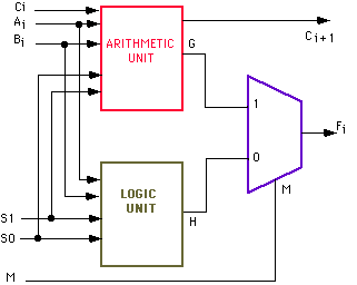
]
PART 1
----------------------------------------------------------------------------------
-- Create Date: 17:03:28 03/22/2011
-- Module Name: Project1
-- Project Name: Lab1
----------------------------------------------------------------------------------
library IEEE;
use IEEE.STD_LOGIC_1164.ALL;
use IEEE.STD_LOGIC_ARITH.ALL;
use IEEE.STD_LOGIC_UNSIGNED.ALL;
entity sequencer is
Port ( clk : in STD_LOGIC;
R0,R1,R2,R3 : in STD_LOGIC;
Kd : out STD_LOGIC );
end sequencer;
rchitecture Behavioral of sequencer is
signal QA,QB : STD_LOGIC;
begin
process (clk)
begin
if clk = '1' and clk'event then
QA <= (R0 or R1 or R2 or R3) or (QA and QB);
QB <= QA;
end if;
end process;
Kd <= QA and QB;
end Behavioral;
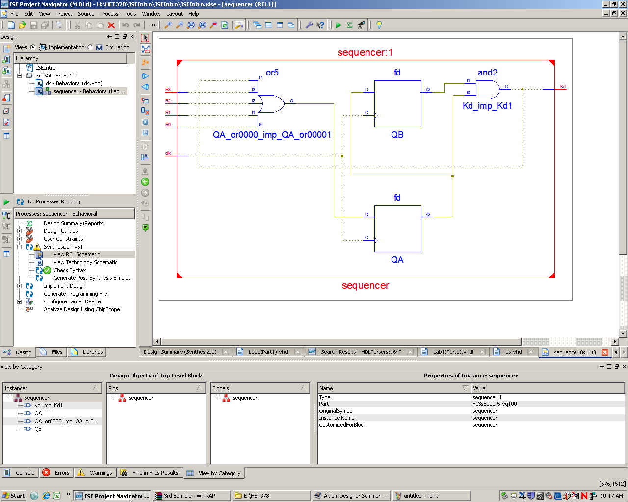
Figure 1 Part 1 Synthesis results
Part 2
----------------------------------------------------------------------------------
-- Company:
-- Engineer:
--
-- Create Date: 10:50:38 03/23/2011
-- Design Name:
-- Module Name: alu - Behavioral
-- Project Name:
-- Target Devices:
-- Tool versions:
-- Description:
--
-- Dependencies:
--
-- Revision:
-- Revision 0.01 - File Created
-- Additional Comments:
--
----------------------------------------------------------------------------------
library IEEE;
use IEEE.STD_LOGIC_1164.ALL;
use ieee.std_logic_unsigned.all;
use IEEE.numeric_std.all;
-- Uncomment the following library declaration if using
-- arithmetic functions with Signed or Unsigned values
--use IEEE.NUMERIC_STD.ALL;
-- Uncomment the following library declaration if instantiating
-- any Xilinx primitives in this code.
--library UNISIM;
--use UNISIM.VComponents.all;
entity alu is
Port ( M : in STD_LOGIC;
SEL: in std_logic_vector(1 downto 0);
CIN: in STD_LOGIC;
A : in STD_LOGIC_VECTOR (3 downto 0);
B : in STD_LOGIC_VECTOR (3 downto 0);
F : out STD_LOGIC_VECTOR (3 downto 0);
CO : out STD_LOGIC
);
end alu;
ARCHITECTURE Behavioral of alu is
signal H : std_logic_vector(3 downto 0);
signal G : std_logic_vector(4 downto 0);
signal sCIN : std_logic_vector(2 downto 0);
Begin
sCIN <= SEL & CIN;
CO <= G(4);
F<=H when M='0'
else G(3 downto 0);
LOGIC:process(SEL,A,B)
Begin
case SEL is
when "00" =>
H <= A and B;
when "01" =>
H <= A or B;
when "10" =>
H <= A xor B;
when "11" =>
H <= A xnor B;
when others =>
null;
end case;
end process LOGIC;
ARTH:process (CIN,sCIN,A,B)
Begin
case sCIN is
when "000" =>
G <= A + '0';
when "001" =>
G <= A + '1';
when "010" =>
G <= A + B;
when "011" =>
G <= A + B + CIN;
when "100" =>
G <= (A + (NOT B));
when "101" =>
G <= ((NOT B) + A + '1');
when "110" =>
G <= ((NOT A) + B);
when "111" =>
G <= ((NOT A) + B + '1');
when others =>
null;
end case;
end process ARTH;
end Behavioral;
Part 2- Testbench
--------------------------------------------------------------------------------
-- Company:
-- Engineer:
--
-- Create Date: 18:38:07 04/05/2011
-- Design Name:
-- Module Name: C:/Users/LAU HUI YON/Lab2Part2/vhdltestbench2.vhd
-- Project Name: Lab2Part2
-- Target Device:
-- Tool versions:
-- Description:
--
-- VHDL Test Bench Created by ISE for module: alu
--
-- Dependencies:
--
-- Revision:
-- Revision 0.01 - File Created
-- Additional Comments:
--
-- Notes:
-- This testbench has been automatically generated using types std_logic and
-- std_logic_vector for the ports of the unit under test. Xilinx recommends
-- that these types always be used for the top-level I/O of a design in order
-- to guarantee that the testbench will bind correctly to the post-implementation
-- simulation model.
--------------------------------------------------------------------------------
LIBRARY ieee;
USE ieee.std_logic_1164.ALL;
-- Uncomment the following library declaration if using
-- arithmetic functions with Signed or Unsigned values
--USE ieee.numeric_std.ALL;
ENTITY vhdltestbench2 IS
END vhdltestbench2;
ARCHITECTURE behavior OF vhdltestbench2 IS
-- Component Declaration for the Unit Under Test (UUT)
COMPONENT alu
PORT(
M : IN std_logic;
SEL : IN std_logic_vector(1 downto 0);
CIN : IN std_logic;
A : IN std_logic_vector(3 downto 0);
B : IN std_logic_vector(3 downto 0);
F : OUT std_logic_vector(3 downto 0);
CO : OUT std_logic
);
END COMPONENT;
--Inputs
signal M : std_logic := '0';
signal SEL : std_logic_vector(1 downto 0) := (others => '0');
signal CIN : std_logic := '0';
signal A : std_logic_vector(3 downto 0) := (others => '0');
signal B : std_logic_vector(3 downto 0) := (others => '0');
--Outputs
signal F : std_logic_vector(3 downto 0);
signal CO : std_logic;
-- No clocks detected in port list. Replace <clock> below with
-- appropriate port name
----constant <clock>_period : time := 10 ns;
BEGIN
-- Instantiate the Unit Under Test (UUT)
uut: alu PORT MAP (
M => M,
SEL => SEL,
CIN => CIN,
A => A,
B => B,
F => F,
CO => CO
);
-- Clock process definitions
----<clock>_process :process
----begin
----<clock> <= '0';
----wait for <clock>_period/2;
----<clock> <= '1';
----wait for <clock>_period/2;
----end process;
-- Stimulus process
stim_proc: process
begin
-- hold reset state for 100 ns.
wait for 100 ns;
----wait for <clock>_period*10;
-- insert stimulus here
M<= '1'; ]
SEL<= "00";
A <= "0000";
B <= "0000"; wait for 0.001 ns;
A <= 0001";
B <= "0001"; wait for 0.001 ns;
A <= "0010";
B <= "0010"; wait for 0.001 ns;
A <= "0011";
B <= "0011"; wait for 0.001 ns;
wait;
end process;
END;

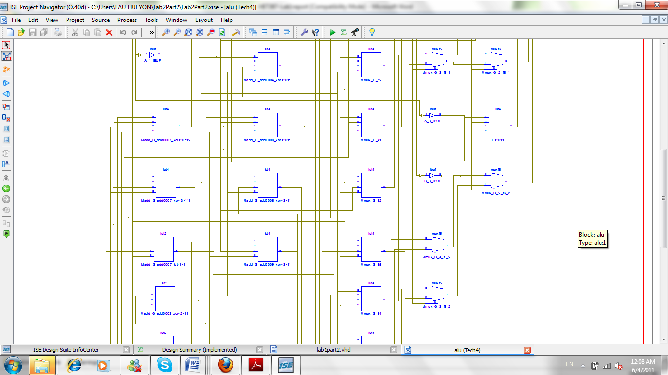

Figure 2 Part 2 4-bit ALU Synthesis results
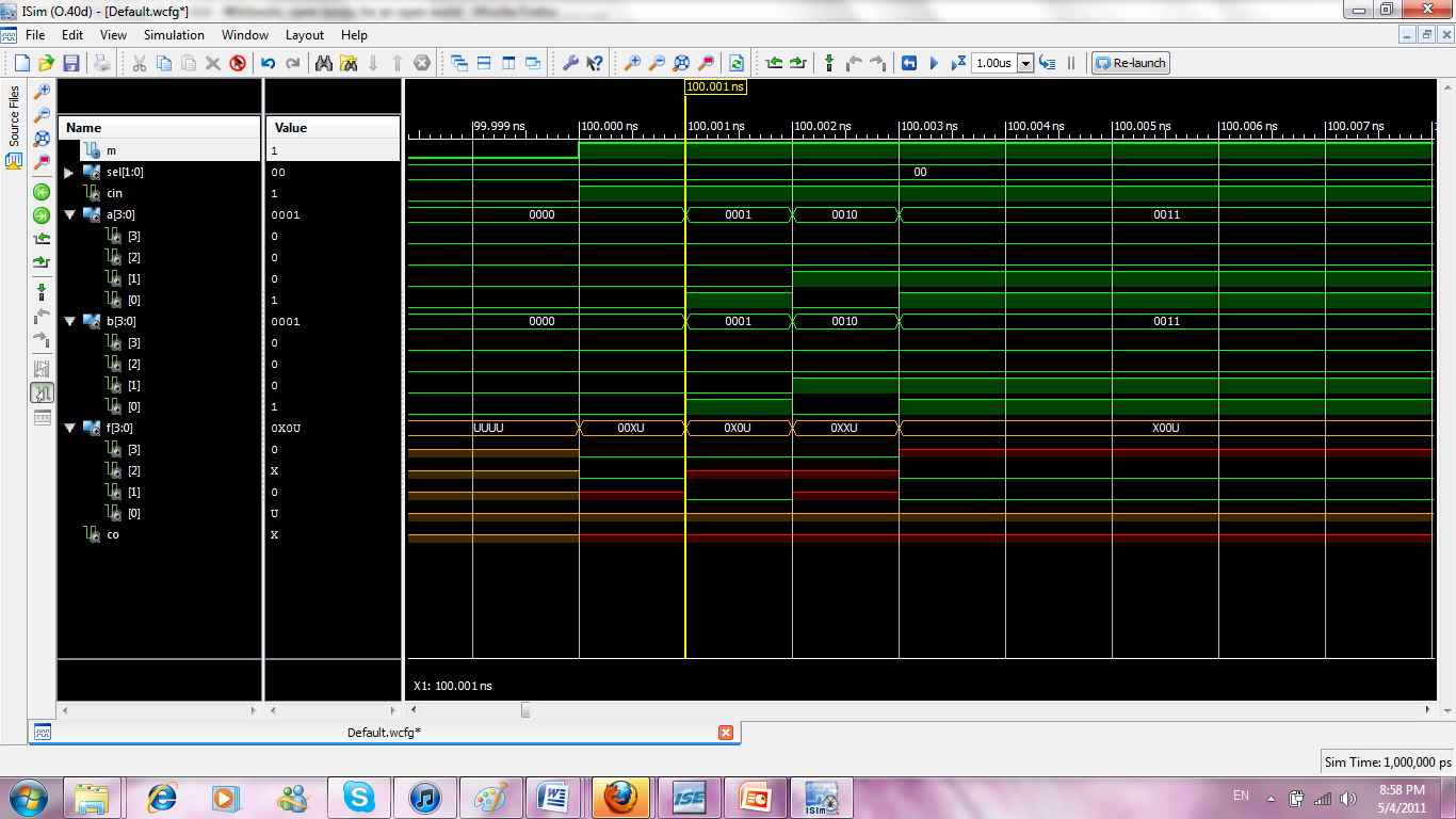
Figure 3 Part 2 testbench Simulation results
Part 2: Extend to 16-ALU
----------------------------------------------------------------------------------
-- Company:
-- Engineer:
--
-- Create Date: 21:32:22 04/05/2011
-- Design Name:
-- Module Name: sixteenbitalu - Behavioral
-- Project Name:
-- Target Devices:
-- Tool versions:
-- Description:
--
-- Dependencies:
--
-- Revision:
-- Revision 0.01 - File Created
-- Additional Comments:
--
----------------------------------------------------------------------------------
library IEEE;
use IEEE.STD_LOGIC_1164.ALL;
use ieee.std_logic_unsigned.all;
use IEEE.numeric_std.all;
-- Uncomment the following library declaration if using
-- arithmetic functions with Signed or Unsigned values
--use IEEE.NUMERIC_STD.ALL;
-- Uncomment the following library declaration if instantiating
-- any Xilinx primitives in this code.
--library UNISIM;
--use UNISIM.VComponents.all;
entity sixteenbitalu is
Port ( M : in STD_LOGIC;
SEL: in std_logic_vector(1 downto 0);
CIN: in STD_LOGIC;
A : in STD_LOGIC_VECTOR (15 downto 0);
B : in STD_LOGIC_VECTOR (15 downto 0);
F : out STD_LOGIC_VECTOR (15 downto 0);
CO : out STD_LOGIC
);
end sixteenbitalu;
architecture Behavioral of sixteenbitalu is
signal H : std_logic_vector(15 downto 0);
signal G : std_logic_vector(16 downto 0);
signal sCIN : std_logic_vector(2 downto 0);
begin
sCIN <= SEL & CIN;
CO <= G(15);
F<=H when M='0'
else G(15 downto 0);
LOGIC:process(SEL,A,B)
Begin
case SEL is
when "00" =>
H <= A and B;
when "01" =>
H <= A or B;
when "10" =>
H <= A xor B;
when "11" =>
H <= A xnor B;
when others =>
null;
end case;
end process LOGIC;
ARTH:process (CIN,sCIN,A,B)
Begin
case sCIN is
when "000" =>
G <= A + '0';
when "001" =>
G <= A + '1';
when "010" =>
G <= A + B;
when "011" =>
G <= A + B + CIN;
when "100" =>
G <= (A + (NOT B));
when "101" =>
G <= ((NOT B) + A + '1');
when "110" =>
G <= ((NOT A) + B);
when "111" =>
G <= ((NOT A) + B + '1');
when others =>
null;
end case;
end process ARTH;
end Behavioral;
Figure 4 Schematic diagram for 16-bit ALU

Figure 5 Part 2 16-bit alu testbench Simulation results
Discussion:
The approach chosen in the implementation of ALU is the design using modular STD_logic functions . The VHDL codings were divided into two models where M=0 and M=1.
The VHDL codings were firstly checked for syntax error and then was synthesized. There were warnings given after the synthesis. After correcting the errors, the codes are run again.
A testbench file was produced. I have several inputs, however, my testbench is only testing the necessary values to determine whether each function is operating correctly.
After researching how ALUs function, the modules required for a structural design were determined to be an arithmetic module, to perform addition, subtraction, increment and decrement operations, a logic unit to perform the logical operations as described above, and a shifting unit to move all the bits to the left or right.
On the arithmetic module, it was noted that the carry in was always tied to the least significant bit on the operation code, so in an effort to increase efficiency, compactness, and to reduce the input pin count used, the carry in value was forced to the least significant bit, and there is no true carry-in on this design.
As the operation code, or op code, is given to each unit separately, and only one operation, and thus, one unit will be active during a specific operation, all three units always receive the op codes, and the result is logically OR’d together. The result of this is that the non functional units return all low signals, and the active unit returns high signals where necessary, so only the active high signals are translated through the ALU.
The test bench waveform of the design can be seen in Figure 3, displaying all functional operation codes as well as the outputs that each function resulted in. The results of the Testbench were simulated in ISIM software. As can be seen by comparing truth table values of the 1-bit ALU to the output values F and Cout, the waveform shows a correct simulation of the given equation. For example, when the select inputs, S0, S1 are 00, A and B are XORED appropriately getting the desired results (Figure 3). When the function changes to S0, S1 = 01, then the result is a NOR function, which can be seen in the waveform. Further, when the S0, S1 = 10, the waveform shows the correct addition and carry bit, and finally, it also shows the correct output for the AND function when S0=S1=11.
In Figure 3, the waveform for the most pertinent values are shown for the 4-bit ALU to verify functionality. Thus, so far the waveform has verified correctness of the circuit.
Conclusion:
The implementation of the code can emphasize efficiency or speed of coding, using a structural design for high constraint designs for such situations as embedded systems that require the strictest coding practices due to size, heat, power draw, and other factors.
As I was completing the project, I found many roadblocks along the way. I found out the “if” statements are considered behavioral code only and that no structural code can be written with “if” statements. Further, I found out that “if” structures have very specific structures that do not mix. Thus, I corrected the situation by creating behavioral code to simulate the functionality. Finally, I learned how to better able to simulate materials in ISIM software by being able to decide which variables to simulate for detecting problems/bugs.
No comments:
Post a Comment